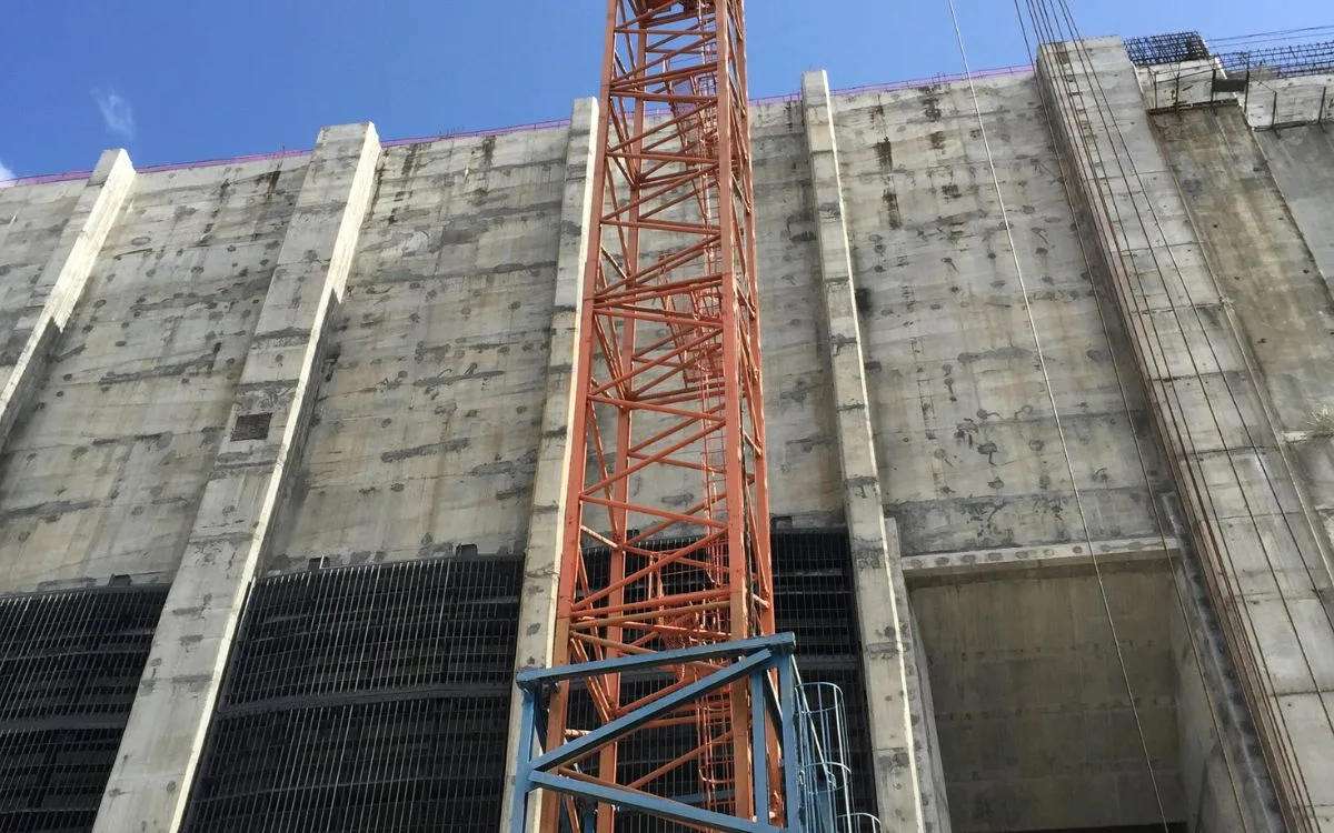
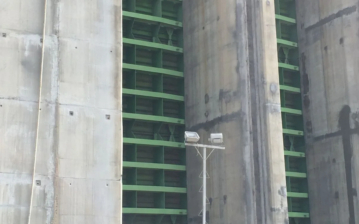
At the Tocoma hydroelectric plant, the intake maintenance gate is what isolates the water intake so the conduit can be dewatered and serviced. Before that gate can be lifted, the pressure across it must be equalized — otherwise the differential hydrostatic head makes the gate impossible to raise safely. That equalization is done by a bypass filling system: an 8-inch ball valve, integrated in the gate and operated by a self-acting counterweight mechanism, that opens to fill and closes to re-seal. When the mechanism designed by the project's contracted engineering firm would not close the valve reliably, ITS de Venezuela — on behalf of ACD America Corp — was brought in to reengineer it, within the works of the Consorcio OIV-Tocoma, the project's main contractor to Corpoelec/Edelca. What follows is how the problem was diagnosed and solved with mechanics, not trial and error.
What the bypass filling system has to do
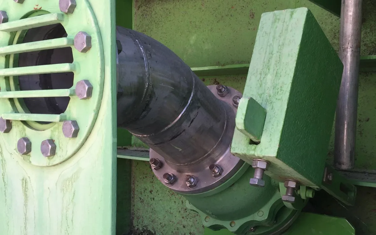
The bypass is a small 8-inch ball valve that equalizes pressure across the intake maintenance gate so the gate can be lifted. It is not motor-driven: a counterweight biases the valve toward closed, and an operator applies a force through a linkage to open it against that counterweight. The whole assembly operates submerged, in raw river water. Two things therefore decide whether it works: the counterweight must guarantee positive closing at the very end of the stroke — its weakest position — and the closing geometry must not exceed the limit that would force the operating key.
The problem: a mechanism that would not close
The original mechanism did not close the valve reliably. Read in mechanical terms, the counterweight and the linkage geometry were not matched to the valve's real closing torque, and the fact that the assembly works submerged — where buoyancy reduces the effective weight of the counterweight — had not been accounted for. The result was a self-acting valve that could not be trusted to re-seal, on a safety-critical function of the plant.
Measure, don't assume: the valve's real torque
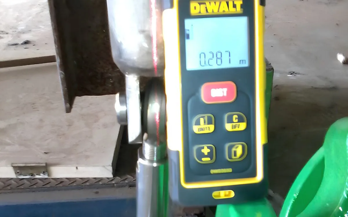
The reengineering started by measuring the valve, not assuming it. The actual resistive torque of the 8-inch ball valve was measured across its motion, and the closing torque was taken as the governing case — because the position where the counterweight has the least capacity to close is precisely the final closing position.
| Operation | Measured torque |
|---|---|
| Opening (breakaway) | 285 N·m |
| Running (displacement) | 210 N·m |
| Closing — governing case | 325 N·m |
Sizing the counterweight — including buoyancy
From the closing torque and the linkage geometry, the required counterweight force underwater is 1,762.5 N. But because the assembly is submerged, its effective weight is reduced by buoyancy — so the physical counterweight has to be heavier out of the water. For the proposed 0.39 × 0.25 × 0.27 m block the buoyant force is 258 N (the hydrodynamic drag, 0.9 N, is negligible), giving a real out-of-water weight of about 206.6 kg. Accounting for buoyancy on a submerged mechanism is exactly the step that a torque-only, dry-assumption design misses.
The forces were then computed across the entire travel of the mechanism (from α = 60° to −30°). The worst case is at startup: the resultant actuating force reaches 25.1 kN. Every downstream component was then checked against that governing load.
Verifying every component by calculation
Each part of the linkage was sized and checked — for static strength, fatigue, buckling and welds — against its material's allowables, with an explicit safety factor. Nothing was left to "looks strong enough."
| Component | Material | Verification | Safety factor |
|---|---|---|---|
| Connecting rod | AISI 316 | Fluctuating-stress fatigue | 2.31 |
| Connecting rod | AISI 316 | Euler buckling | 22.4 |
| Pin | 17-4 PH | Shear | 7.86 |
| Pin | 17-4 PH | Bending | 4.56 |
| Rod end (FK JMX12T) | Alloy steel / 52100 ball | Radial load | 4.97 |
| Beam fork | AISI 304 | Bending | 3.86 |
| Counterweight-bar fork | ASTM A572 Gr.50 | Bending | 12.23 |
| Counterweight bar | ASTM A572 Gr.50 | Shear at pivot | 3.99 |
Modeling, drawings and delivery
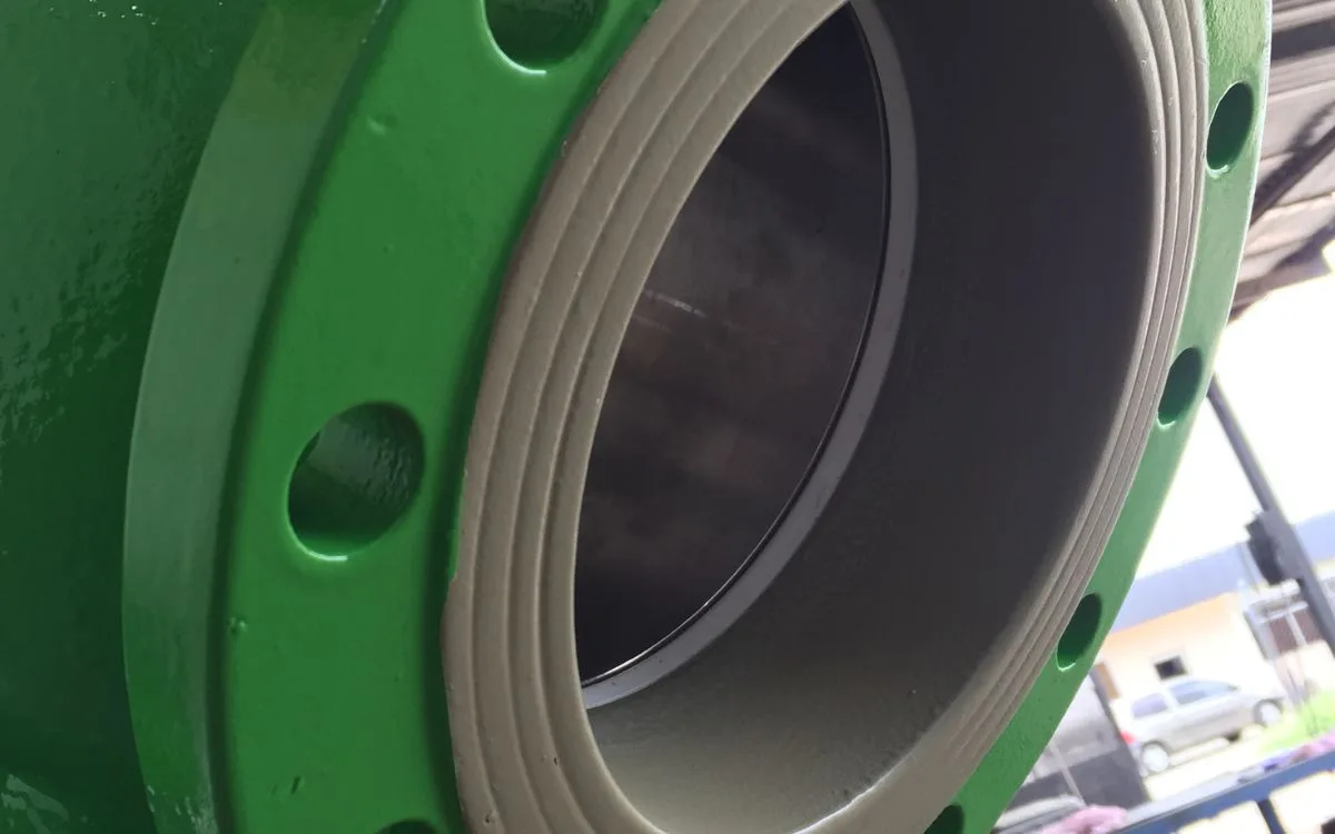
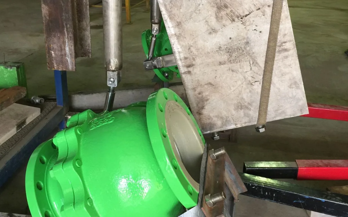
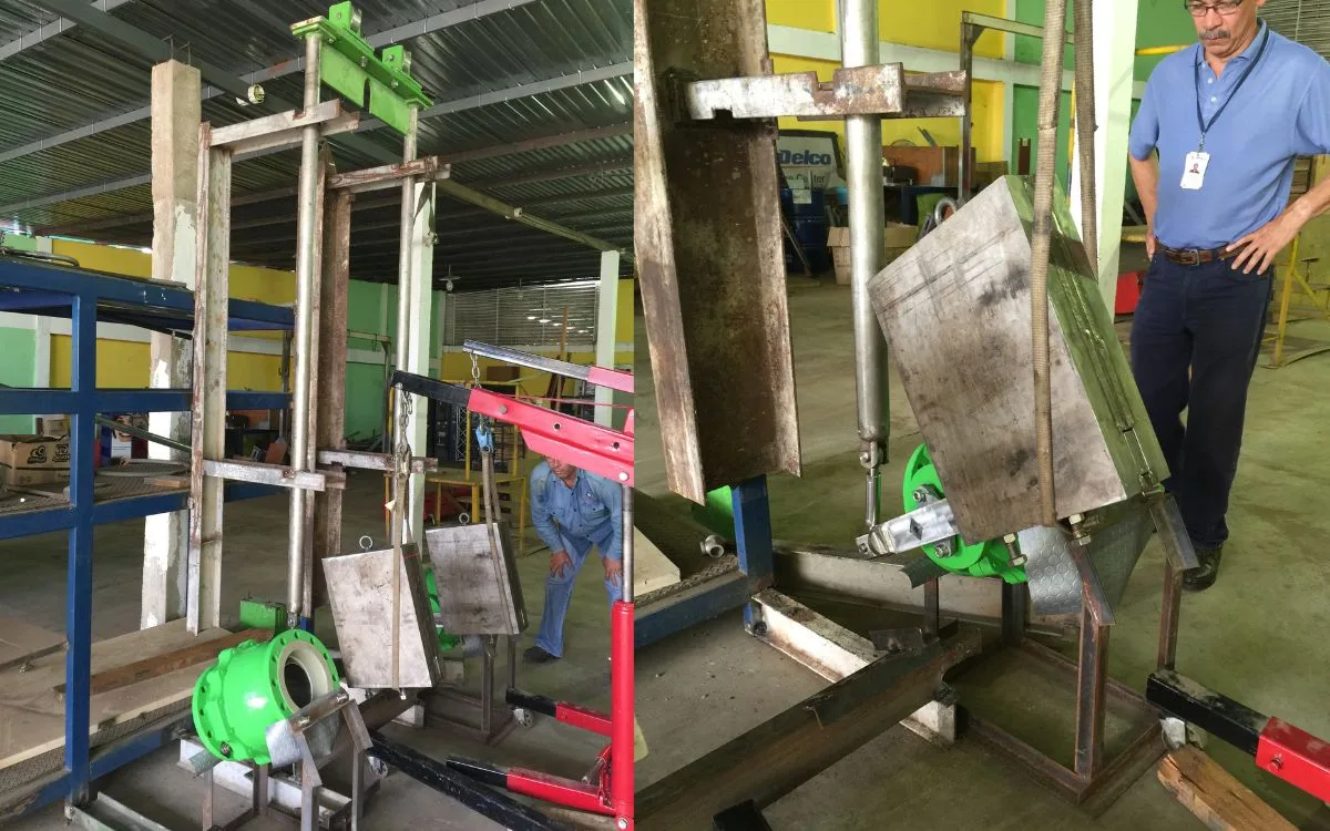
The mechanism was modeled and calculated in Autodesk Inventor, and the welded joints were designed to AWS electrode selection (E308-16 and E7018 classes). ITS de Venezuela delivered the full package on behalf of ACD America: the calculation memoir, the fabrication drawings, a shop-tested model of the mechanism, and the reconditioning and recoating (white-metal blast, epoxy primer and polyurethane finish) of the 8-inch bypass ball valve itself.
Why it matters
This was root-cause mechanical engineering: a submerged, self-acting mechanism diagnosed by measurement, sized with the physics that actually govern it (closing torque and buoyancy), and verified component by component with safety factors — succeeding where the previously contracted engineering had not. It is the clearest expression of what ACD, through its engineering group ITS de Venezuela, brings beyond supply: the ability to solve the mechanism, not just furnish the parts.
Technical leadership
The mechanical calculations and the 3D modeling in Autodesk Inventor were led by Carlos E. Rojas — today Regional Sales Leader at ACD America Corp — for ITS de Venezuela, the engineering company of the ACD America group, on behalf of ACD America Corp.
Represented manufacturers & end user
- ITS de Venezuela Engineering execution — ACD America group company
- Consorcio OIV-Tocoma Project consortium — main contractor
- Corpoelec / Edelca ↗ End user (client)
Frequently asked questions
Why is the bypass valve operated by a counterweight instead of a motor?
Because the mechanism is a simple, self-acting device integrated in the intake maintenance gate: the counterweight biases the valve to closed and an operator opens it manually, so it re-seals on its own without power or instrument air — provided the counterweight is correctly sized.
Why did buoyancy matter in the calculation?
The whole mechanism operates submerged. Buoyancy reduces the counterweight's effective weight underwater, so the physical counterweight must be heavier out of the water — about 206.6 kg for the required 1,762.5 N underwater. Ignoring it under-sizes the counterweight and the valve fails to close.
Which standards and tools were used?
The mechanism was modeled and calculated in Autodesk Inventor; component safety factors were computed against material allowables (AISI 316, 17-4 PH, AISI 304, ASTM A572 Gr.50) and the welds designed to AWS electrode classes (E308-16, E7018).
Who executed the engineering?
ITS de Venezuela, the engineering company of the ACD America group, on behalf of ACD America Corp — with the mechanical calculations and 3D modeling in Autodesk Inventor by Carlos E. Rojas, today Regional Sales Leader at the corporation.
A demanding valve service of your own?
Tell us the process, the fluid and the duty — our application engineers help specify, source and verify the right valves for severe service.