+1 866-700-9858
6923 Narcoossee Rd. Ste. 612
Orlando, Fl. 32822
NEWSROOM
ACD America Corporation’s Commitment to Excellence in Control Valves and Instruments for the Process Industries
Simplifying Control Valve Packing Selection

The traditional valve selection process has historically involved choosing a valve design based on flow performance, material compatibility, pressure and temperature capabilities, and related factors. Control valve packing selection was often a relatively minor issue, based largely on the process temperature. However, valve packing selection has become significantly more important with the passage of regulations, such as the USA Clean Air Act Amendments by the Environmental Protection Agency (EPA). Emissions limits were 500 ppm, but have dropped to 100 ppm, and even 50 ppm in some cases.
This article will explain details regarding valve packing and its selection, and it will provide end users with the information they need to make the best choice for their application.
What is packing?
Before delving into the selection process, it is best to understand what control valve packing does and how it works. Control valves generally fall into one of two major categories — sliding stem or rotary. A sliding stem valve has a rod protruding from the body that rises and falls to open and close the valve. A rotary valve has a shaft extending out the side of the valve that is connected to a ball, disc or plug. As the shaft turns, the rotary valve opens and closes. In either case, the valve stem must exit the body and be capable of relatively friction-free movement, while containing the process and avoiding leaks. Valve packing makes that possible.
The sealing portion of a valve packing usually consists of a series of Teflon (PTFE) or graphite rings that encircle the valve shaft (Figure 1). The rings are compressed with a combination of a packing follower, packing flange and bolts — which push down and squeeze the packing rings against the shaft to seal against process leaks.

Figure 1: This picture shows a typical rising stem control valve. The packing consists of the packing box (#3), the packing rings just above it (#2), and the packing follower, packing flange and bolts mounted above.
The compressed rings allow the valve stem to move, while maintaining a seal against the valve body and shaft to keep process fluids from leaking along the stem and escaping. In certain applications, the packing need only protect against gross process leaks, so relatively minor fugitive emissions were not a concern. Free stem movement was considered a more important requirement, since a stuck or bound valve stem would impact a valve’s ability to control flow.
Packing designs were simple, and so was packing ring selection, as it was primarily based on process temperature since only very high process pressures impacted packing. All that changed when fugitive emission reduction became a priority for the EPA. Valve packing emissions for hazardous and targeted chemicals were initially capped at 500 PPM but have been steadily dropping with each round of regulation. Packing design options are now much more varied, complicating the selection process.
Environmental packing designs
To maintain such low emissions, packing must be “live loaded” to keep constant pressure on the sealing rings (Figure 2). This is usually accomplished using spring-loaded Belleville springs, which are compressed during installation. The Belleville springs maintain a constant force on the packing, ensuring it seals over time, even as the rings wear from stem movement. The loading of the packing must be higher than the process pressure, which further complicates the design and selection process.

Figure 2: Modern packing design uses compressed Belleville or other special springs to maintain constant pressure on the packing rings. This ensures the fugitive emissions are limited to 100 PPM or less, even as the rings wear.
Live loaded packing designs greatly reduce fugitive emissions, and the higher the compression, the lower the leak rate. However, high compression increases stem friction, hampering movement and degrading control valve performance. PTFE seals well and lubricates the shaft, allowing smooth motion, but PTFE packing is generally only rated up to 450°F at limited pressure. Above that temperature, it tends to break down, emitting toxic gases and corroding the valve stem.
Graphite rings can be employed instead of PTFE, greatly increasing the allowable temperature to 1,000°F and pressures to over 4,000 PSI. However, graphite does not seal nearly as well as PTFE, making it difficult to comply with emission regulations. It also tends to restrict stem movement at lower temperatures, degrading performance.
Advanced environmental packing designs
Some valve vendors have addressed these issues through a combination of advanced materials and improved packing configurations (Figure 3). Carbon or glass reinforced PTFE improve wear properties, and combination packing consisting of layers of graphite and reinforced PTFE extend the operating range. There are also alternative materials, such as KALREZ, which may be more suitable for certain difficult process chemicals.

Figure 3: Advanced environmental packing arrangements use carbon reinforced PTFE, graphite, or combinations of reinforced PTFE and graphite rings to handle higher process temperatures and pressures, yet still achieve an emission rate less than 100 PPM.
Despite these improvements, there are some environmentally sensitive applications where the process conditions exceed the temperature and pressure ratings of the packing. In such situations, there is yet another option.
High temperature modeling
In most control valves, the packing is located on the valve stem and relatively distanced from the valve body. While the valve internals are subjected to the full temperature of the process, the packing usually encounters less temperature since the valve bonnet tends to radiate heat away. The temperature differential between the process and the packing provides an opportunity to utilize the superior sealing and lubrication of PTFE-based packing in applications where the process media exceed the PTFE temperature rating.
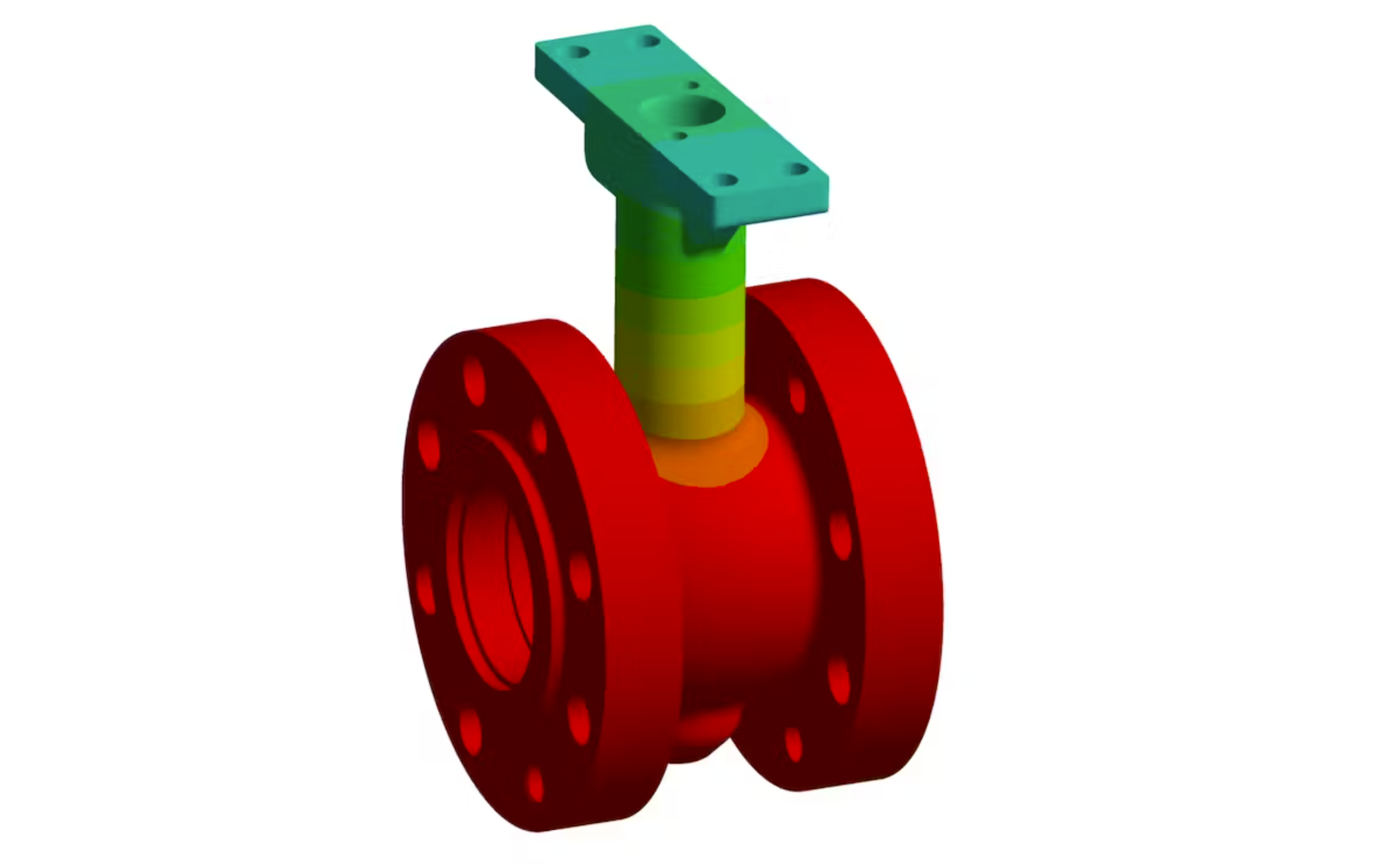
Finite element analysis can be employed to model the heat signature of a control valve body and bonnet during process conditions (Figure 4). This thermal model can be used to predict the maximum temperature encountered by different sections of the packing.

Figure 4: Advanced modeling and simulation programs allow vendors to predict the maximum temperature of the packing components, allowing superior performing packing materials to be utilized.
The accuracy of these simulation models is based on an advanced understanding of the valve’s convection, radiation and conduction, as well as extensive lab testing (Figure 5). The result of this effort enables high performance packing materials to be applied in process conditions well beyond their standard ratings of PTFE-based packing.

Figure 5: This control valve is subjected to temperature cycling in a lab to develop temperature simulation models and verify their accuracy.
Once temperature models are created and validated, the data can be used to create a packing design that might include a combination of graphite packing in the high temperature zones and reinforced PTFE packing in the lower temperature areas. The graphite handles the high temperature and pressure. The PTFE ensures the emission requirements are met, while providing improved lubrication and longer service life.
End users should look for vendors offering all these options, and work with them to select the right combination for their application.
Packing selection summary
Control valve packing selection requires end users to follow these steps in sequence:
- Determine the pressure and temperature of the process media.
- Know the valve type (rising stem versus rotary) and valve manufacture and model (which may limit the available packing options).
- Determine if the valve must meet specific fugitive emission standards or not. (Air, steam, nitrogen, water, etc. would generally not require low emission packing. Natural gas and most hazardous chemicals would typically require low emission performance.)
- Investigate the material compatibility of the process with the various packing seal options offered by the valve vendor.
- Based on that information, consult the packing options for the chosen valve model to determine what packing materials and designs will meet the requirements. The selected packing should provide the required level of emissions, while minimizing stem friction movement as much as possible. Note that even though a process may not require low emission packing, some environmental packing designs may be a good option since they may provide superior sealing performance and very low friction.
- If a standard packing offering is not rated for the temperature and pressure conditions, investigate if the valve vendor has temperature models available which might enable a combination of packing materials to meet the application’s requirements.
Conclusion
Historically, control valve packing design has been a relatively simple part of the control valve selection process. A specific control valve was selected based on the required flow performance, process temperature and pressure, and the packing was simply supplied by the vendor to match the process data provided by the end user.
Now, packing selection and design is much less obvious. Stringent environmental regulations demand very low emissions from the valve packing over the life of the valve, yet the packing must simultaneously allow relatively friction-free movement. This has driven the development of much more advanced valve packing designs, which must be carefully evaluated and correctly applied to deliver high performance and maintenance free service.
End users can address these and other issues by working with a valve vendor offering not only a wide range of options, but also the capability to evaluate various designs and verify the suitability of each for their application.
Wade Helfer is a technologist at Emerson Automation Solutions and is responsible for developing and evaluating new technologies with an emphasis on mechanical systems. He has 23 years of industry experience in the design and evaluation of control and isolation valves for a variety of industries. He completed his BS degree and graduate coursework in mechanical engineering from Iowa State University.
Sarah Witte is a simulation engineer at Emerson Automation Solutions. She has four years of industry experience at Emerson in the evaluation of control and isolation valves utilizing Finite Element Analysis with a focus on thermal analysis. She completed her B.S. degree in Mechanical Engineering from Iowa State University.
Emerson
Category
Tag List
Recent Posts


